Transformer Parasitic Model for High Frequency Applications

The analysis and design of transformer in high frequency applications involve identification of different parameters contributing to the electromagnetic energy conversion and current flow within the circuit. The interrelation of dependent and independent parameters are represented by mathematical formulation in the transformer model. The choice of modelling depends on the field of interest and the application area. The design objective is to enhance the energy conservation techniques and reduction of the power wastage in the form of heat, noise and electromagnetic radiations.
The modeling of transformer constitute in two parts, representation of winding and representation of core. Both of these are frequency dependent in nature. The characterization of winding includes flux generation, flux conversion, wire resistance, stray inductance and stray capacitance, which are mostly driven by linear equations. Characterization of core is non-linear and associated with flow of magnetization flux within the geometry.
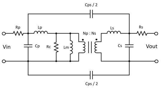
Figure 1: Transformer parasitic model
Figure 1 represents transformer model for medium to high frequency applications.The electric isolation and voltage conversion is represented by Np:Ns turn ratio. The magnetization inductance, Lm contribute to reactance seen by the primary side of the circuit. Both of these components assumed to be loss less. Remaining elements in this model represent various losses associated with the transformer. The Lp and Ls are primary and secondary Leakage Inductance, Rp and Rs are primary and secondary Wire Resistance, Cp and Cs are primary and secondary Leakage Capacitance respectively. Rc is Core Resistance responsible for core loss and Cps is Mutual Leakage Capacitance that appear due to proximity of primary and secondary winding and the dielectric material in between them. The Mutual Leakage Capacitance is distributed throughout the body of transformer, for simplicity it is shown as equally divided at each side of connecting wire.
Leakage Inductance:
The equivalent circuit of transformer neglecting core loss and stray capacitance is shown in Figure 2. The Leakage Inductance, Lp is connected in series with Magnetizing Inductance, Lm at the primary side of the transformer. This leakage inductance appears due to the leakage flux that doesn’t induce current in secondary winding. This leakage inductance in conjunction with stray capacitance creates resonance effect for high frequency elements in pulse waveform. This can be seen as overshoot and ringing at the voltage or current switching instances. Similarly, the Leakage Inductance at secondary side is denoted as Ls and shown in series connection with secondary winding.
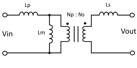
Figure 2: Transformer equivalent circuit for leakage inductance
The total Leakage Inductance, Leq seen at the primary side is given by the equation below, where Np and Ns are primary and secondary winding turns respectively.
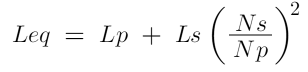
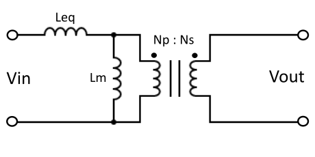
Figure 3: Total leakage inductance referred to primary side
Skin Effect:
The DC current flows through the center of the conductor whereas high frequency AC current flows through surface of the conductor, this is called skin effect. The skin depth is inversely proportional to the square root of frequency. The computation of wire resistance in high frequency application depends on conductor surface area. There are several procedures to mitigate skin effect, using litz wire or flat wire conductors are popular among them.
Proximity Effect:
The high frequency AC current induce magnetic fields to other wires in the vicinity. This inducted alternating magnetic fields cause distortion of current density in conductor that affects transformer efficiency. In high frequency application loss due to proximity effect can be significant. To minimize it, winding layer count need to be reduced.
Fringing Flux:
Fringing Flux appear in between core gap. Fringing flux decreases the reluctance of magnetic material therefore increases the inductance. When some part of these flux lines intersect winding or core material perpendicularly, eddy current is produced. Which causes heating loss and overall transformer efficiency is reduced.
Leakage Capacitance:
There are several source of leakage capacitance within transformer. Some of them are indicated in Figure 1. Wherever insulation or dielectric material get trapped in between two conductive layers with different potentials, stray capacitance is generated. Stray capacitance sources are found in primary winding, secondary winding and among interleaved layers of primary and secondary windings. It can also be found in between adjacent turns in all the windings. Even small values of stray capacitance can create unwanted effects in high frequency applications. It is not possible to completely get rid of stray capacitance, though it can be controlled within specified tolerance range in specialized manufacturing techniques. Careful choice of transformer shape and construction can minimize the stray capacitance.
Advancement in electronic design has shown intelligent application of transformer parasitic elements in favor of reduction in circuit component count, overall compact size, higher efficiency and increased power density.
Lithentic Technologies specializes in high frequency transformer and inductor design and production. Our transformers and inductors have tight tolerance range for vital parameters and reduced parasitic elements. We employ automated quality check for every components produced which guarantees error free device functioning, zero rejection and customer satisfaction. Please reach to us by phone, whatsapp, email or direct chat by clicking here.