How to easily generate DC voltage at home?
DC or Direct Current is used in almost all electronic circuits in our household appliances, computer, mobile, car, laboratory equipment and what not! So there is one AC to DC converter in each of these equipment, like your laptop charger, mobile charger, EV Charger where the power source is AC from wall socket. The refrigerator, TV, washing machine, microwave and other household appliance that connect to wall socket also has AC to DC converter within their enclosure. The other DC source is batteries, could it be inverter battery, car battery or that fitted in your TV remote.
We shall discuss about the AC to DC conversion process in details here. We shall also look into different circuits that are easy to make for this purpose in cheaper price.
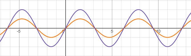
Figure 1: Single phase AC sinusoidal voltage and current
The mains AC voltage is 650 Volt peak-to-peak 50 Hz sinusoidal waveform as shown in Figure 1 in most of Asia, Europe and Australia, commonly known as 230 Volt-rms. In North America it is 110 Volt-rms or 312 Volt peak-to-peak 60 Hz waveform. Figure 1 shows the orange sinusoidal as current waveform which has zero phase difference with purple color voltage waveform.
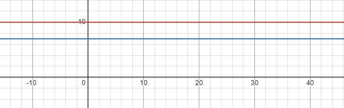
Figure 2: DC voltage and current
The DC voltage is constant amplitude waveform as shown in Figure 2. The current waveform is also straight horizontal line if voltage applied across simple resistive load.
Now we know the AC and DC voltage waveform, lets analyze how our AC to DC converter would work. There are three main tasks, first we need to smooth out the sinusoidal waveform into constant amplitude output, secondly we need to reduce the amplitude of the voltage according to our need and thirdly we need some protection from the high voltage AC power, also known as isolation, to avoid hazards. There are other complex issues like reduction of electromagnetic radiation, prevention of noise reflection back into mains etc. but we shall keep them aside for now and understand the above three tasks for our converter design.
The Rectification
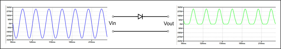
Figure 3: Rectification with single diode
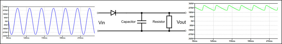
Figure 4: Rectification using single diode and capacitor
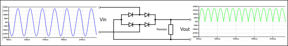
Figure 5: Rectification using bridge rectifier
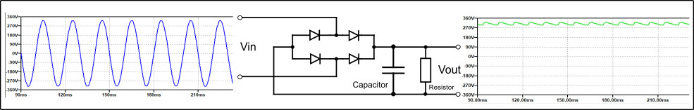
Figure 6: Rectification using bridge rectifier and capacitor
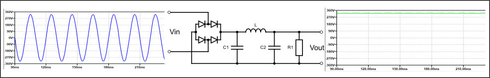
Figure 7: Rectification using bridge rectifier with Pi filter